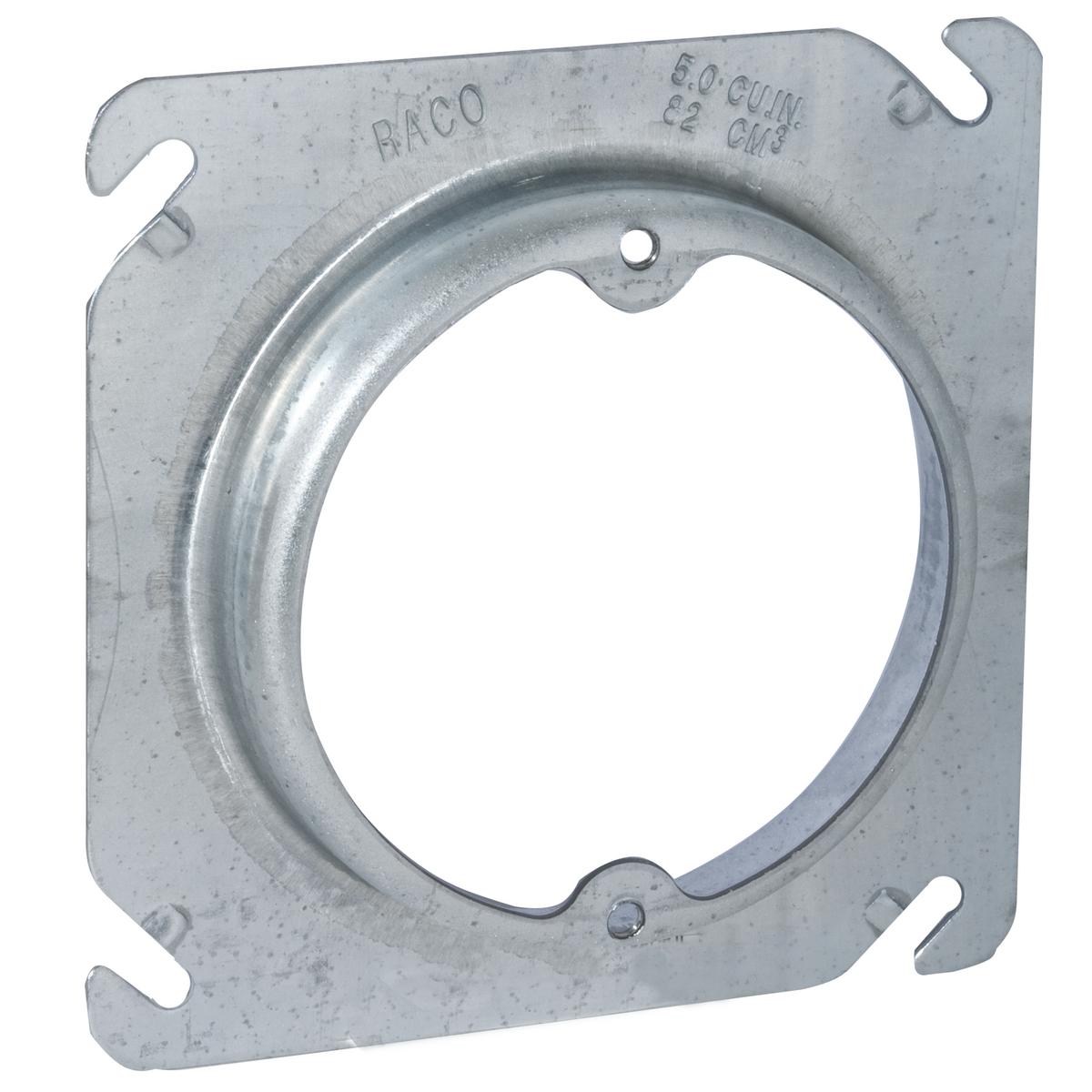

One or more internal cable clamps in the box are counted as one conductor volume in accordance with the volume listed in Table 314.16(B) based on the largest conductor that enters the outlet box ( Fig. Fixture wires smaller than 14 AWG from a domed luminaire or similar canopy aren't counted. This includes equipment bonding jumpers and pigtails ( Fig. If no part of a conductor leaves the box, it shall not be counted. In no case can the volume of the box and its assembled sections be less than the following fill calculations.Įach conductor that originates outside the box and terminates or is spliced within the box must be counted as one conductor.Ĭonductor running through the box Each conductor that runs through the box is counted as one conductor. Table 314.16(A) doesn't take into consideration the fill requirements of clamps, support fittings, devices or equipment grounding conductors within the outlet box. 2: Using Table 314.16(A), how many 14 AWG THHN conductors are permitted in a 4×1.5-inch round box? Note that insulation isn't a factor.Įxample No. This answer comes directly from Table 314.16(A), which permits nine 12 AWG conductors in this size box. The answer is (b), 4×1.5-inch square box. 1: What size outlet box is required for six 12 AWG THHN conductors and three 12 AWG THW conductors? Let's work through a few examples to clarify the calculation.Įxample No. Note: Table 314.16(A) only applies if the outlet box contains no switches, receptacles, luminaire studs, luminaire hickeys, manufactured cable clamps, or grounding conductors, although this is unlikely. When the conductors running to the box are all the same size (insulation doesn't matter), you can use Table 314.16(A) to determine the number of conductors permitted in the outlet box or the size outlet box required for the given number of conductors. Sizing boxes when all conductors are the same size. The volume of a box includes its assembled parts, including plaster rings, industrial raised covers, and extension rings. The minimum box volume must allow for conductors, devices, and fittings. In fact, Table 314.16(A) tells you the size of the most common standard boxes and how much they can hold.
#Plaster rings size install#
Screw Openings Match the Device - The placement of the screw hole is determined by the device that will be placed in that particular position.Have you ever wondered if the outlet box you're planning to install is large enough? What if a box doesn't even have its capacity marked on it? The answers to those questions lie in the requirements of Art. On multiple-gang switch plates, the width between devices (left to right) will be 1-13/16". Screw Spread Remains Constant - Note that screw spread does not change on oversized or narrow plates - it remains a standard measurement no matter the size of the cover plate.

The actual opening at the bottom of this taper is only 3/16" across even though the recessed area is about 5/16" in diameter. On switch plates, the opening has a tapered recess to allow room for surface of a 6/32 domed screw to sit flush with the surface. Below are all the standard screw placements and the types of switch plates with which they are used.Ĭenter-to-Center Spacing - Screw hole spread is measured from the center of one opening to the center of the other (top to bottom on a vertically oriented cover the distance between each screw left to right on a multiple-gang plate is a standard 1-13/16"). This spread is consistent no matter where the opening is on a plate. The length of the spacing between screw hole positions on a switch plate is dependent upon the device opening. Learn more about the types and sizes of Electrical Device & Cover Plate Screws.


 0 kommentar(er)
